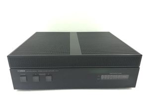
| Form Factor | Standard Width |
| Signal Path | Analog Hardware |
| Dimensions | 43.5 × 14.5 × 37.4 cm (W × H × D) |
| Weight | 18.5 kg |
| Power | Mains |
| Frequency Response | 10 Hz - 100 Khz (8 Ohm, 50 W, 0.02% THD) |
| Rated Power 8 Ohm | 100 W/ch (20 Hz - 30 Khz, 0.005% THD @ 8 Ohms) |
| Rated Power 4 Ohm | 170 W/ch (20 Hz - 30 Khz, 0.005% THD @ 4 Ohms) |
| Intermodulation Distortion | <0.002% @ half rated power |
| Bandwidth | DC - 100 KHz (-0.7 / +0.5 dB) |
| Damping Factor 8 Ohm | 200 |
| Damping Factor 4 Ohm | 100 |
| Stereo Separation | 118 dB (IHF-A) (90 dB @ 1 Khz
70 dB @ 20 Khz) |
| Max Power Consumption | 900 W |
| Channels | 2 Channel |
| Connections | - Analog Stereo · RCA (Phono, Cinch)
- Ground · Binding Post
- Speaker A · Spring Terminal
- Speaker B · Spring Terminal
|
| Controls | - Power · Latching Push Switch · On/Off
- Speaker A · Latching Push Switch · On/Off
- Speaker B · Latching Push Switch · On/Off
- L-ch Trim · Rotary Pot · 0-10
- R-ch Trim · Rotary Pot · 0-10
- Input Coupling Mode · Slide Switch · AC-DC
|
| Displays | - LED · Power · Watts / 8 Ohm
- LED · Overload · Watts / 8 Ohm
|
| Links | http://www.thevintageknob.org/yamaha-M-4.html |
| Notes | A smaller and less powerful followup design to the M-2 introduced earlier. The Japanese version is called the B-2 and is sufficiently different from the M-4 to not be included here. This is a class AB transistor design conservatively rated at 170 Watts per channel into 4 ohms and capable of driving most loudspeakers, including inefficient designs and those with difficult impedance curves. It has Yamaha's typical refined sound for the period. Some M-4 amplifiers include a voltage selector switch. The original sale price was ¥250,000 in 1979.
Other features:
• Gold-plated RCA inputs
• Gold-plated speaker outputs
• 2.5 mm pure copper bus
• Phase-corrected polystyrene caps
• Ground termination
• AC-DC input coupling selector
Excerpt from the owner's manual:
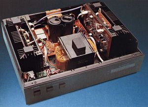
"The voltage amplifying stage employs a cascode-connected differential two-stage circuit throughout.
The use of a Dual FET input and a new cascode bootstrap circuit in the first stage and a cascode-connection, current-mirror and push-pull output in the pre-driver stage ensures a high degree of stability, low distortion and improved high-frequency characteristics.
In the driver and the power amplifier, a three-stage emitter follower is paralleled with pure complementary OCL SEPP circuitry using high-fT transistors. This accounts for wide bandwidth, high output and low distortion.
Two extremely large 15,000µF capacitors, two separate constant-voltage power supplies for the voltage amplifying stage, and the use of a pure copper plate earth line for ultra-low impedance guarantee greatly reduced intermodulation distortion, improved separation and absolutely stable operation.
Except for the chemical capacitors in the power supply section, mylar and styrol capacitors are employed throughout ; layout of parts, wiring, earth line as well as many other aspects have been given due consideration." |