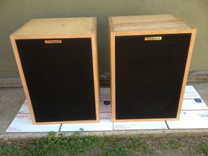
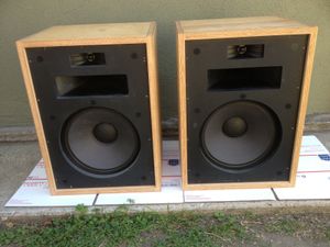
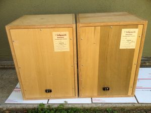
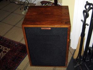
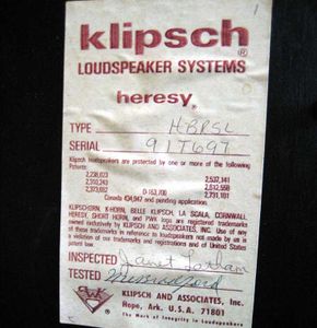
| Notes | History and Content of Klipsch H-700 / Heresy 1
2/25/2005 MK
Klipsch H-700 / Heresy I
Production Dates: Approximately 1967 thru 1985. The H-700 and the Heresy are the same speaker with a name change. The date of the name change is unknown to us at this time without time consuming research of old, poorly organized records. It is believed to have changed in the early 1970s
Dimensions: Approximately the same as current Heresy II
Weight: Somewhat less than the current Heresy II which is made of veneered MDF. The H700 and the Heresy used Birch plywood for the unfinished versions and veneered lumber core for the finished models. Both materials are somewhat lighter than MDF.
Impedance: Same as today 8 Ohm nominal. 16 Ohms was stated at the time due to a different measurement technique
Power handling:It was rated at 25 watts at the time but the testing procedure was very different than it is now so it's difficult to draw a comparison. I have information from later production that states 105 watts which also suggests improvements in power handling due to new types of high temperature resistant adhesives used in the construction of the later drivers.
Sensitivity dB: Approximately the same as today 96dB 1W / 1M
Network: See attached schematic of the Type E network. Several versions were used during the production run, Type C, Type E and Type E2 but the basic design remained the same.
Type of components of network (caps oil and paper; choke coil): Typically oil type caps and iron core inductors
Woofer
Type and name of woofer; K-22
Power handling; 100 continuous
BxL; 14.0 TM
Sensitivity; SPLo = 93.27dB (o= 1.34% / @ Eg=2.83v)
Impedance; Znom= 8.0 ohm
Voice coil diameter; 2”
Material of cone; Pulp
Material of suspension; Treated cloth
Material of magnet; First versions were Alnico then were changed to Ferrite/ ceramic in the mid 1970’s.
Midrange horn
Type and name of midrange horn; K-700
Material; Cast aluminum
Vertical dispersion; 40 degrees
Horizontal dispersion; 90 degrees
Midrange driver
Type and name of midrange driver; K-55-V
Power handling; 30 watts continuous
Sensitivity; 107 dB
BxL; Unknown
Impedance; 10 Ohm DCR / 16 Ohm Nominal
Voice coil diameter; 2” Dia
Material of diaphragm; Phenolic
Material of magnet; Alnico
Tweeter
Type and name of tweeter; K-77
Type and material of horn; Cast Zinc
Power handling; 10 watts
dB; Approximately 105 dB
BxL; Unknown
Impedance; 6.1 DCR / 8 Ohm nominal
Voice coil diameter; 1” Dia
Material of diaphragm; Phenolic
Material of magnet; First versions were Alnico then were changed to Ferrite / ceramic in 1979.
The original Type H, that used the K-1000 midrange horn (which preceded the H-700 / Heresy I) was conceived as the original center channel for the Klipschorn.
Difference between the H-700 and Heresy: It was just a change in name or designation. There were small changes in the drivers and network part values but the basic configuration remained unchanged from 1967 to 1985.
Heresy I production dates: Unknown at this time. It is believed to have changed in the early 1970s
Difference in price of one pair of H-700 / Heresy I’s at the beginning and at the end of production;
$188.00 ea to $225.00 ea in 1967 depending upon cabinet finish at the start of production. I don’t have a price sheet from the year (1985) when we transitioned from the Heresy I to the Heresy II. I do have one from 1987 and the Heresy II ranged from $370.00 ea to $455.00 ea depending on finish and riser options
Difference from Heresy one and Heresy II;
Cabinet: Non removable back panel, the drivers are front mounted in step routes on the baffle instead of rear mounted.
New woofer K-24 (originally built by Klipsch), similar to the K-22 but a revised design. Subsequently sourced from an outside supplier
New midrange driver, K-53 (originally built by Klipsch), similar to the K-55 but a revised design. Subsequently sourced from an outside supplier
New Tweeter, K-76 (originally built by Klipsch), Quite different from the K-77 in design. Subsequently sourced from an outside supplier
New network to match all of the new drivers using binding posts mounted on an input cup, and film capacitors and inductors mounted on a PCB |