| Notes | Basic features
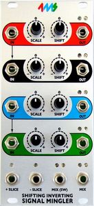
•Four independent voltage processor channels, with four mix/mingle outputs
•Each channel has:◦Input jack
◦Scale knob (from inverted unity, to zero, to unity
◦Shift knob (adds/subtracts DC offset from -9V to +9V)
◦Output jack
◦Red and blue LEDs to indicate + or - voltage, as well as intensity
•MIX jack outputs sum of all channels
•MIX SWitch jack outputs sum of all channels with nothing plugged into their output jack
•+ SLICE jack outputs positive portion of mix (voltages greater than 0V)
•- SLICE jack outputs negative portion of mix (voltages less than 0V)
•Red and blue LEDs on all four mix/mingle jacks display what the signal is doing
Advanced features •Channels 1+2 and 3+4 are normaled together on the input, so plugging into Channel 1 (or 3) will split the signal: A jumper can disable this normalization
•Scale knob has three ranges that are selectable with jumpers: ◦Bi-polar: -1x to +1x (inverting unity to unity) --default
◦Uni-polar: 0 to +1x (level fader)
◦Boost: 0 to 2x (twice the voltage gain)
•Input Header (2x4) for connecting the output of a QCD or QPLFO to the SISM's inputs. Plugging into the input jacks overrides the signal on the header
•Output Header (2x4) for connecting to the input of a VCA Matrix or other compatible module
•PAD breakout header (2x4) for connecting to a breakout module that applies a pre-set pad (attenuation) to each channel. |